Manuals

nordictrack service manual

NordicTrack service manuals are essential tools for maintaining, troubleshooting, and repairing your fitness equipment․ They provide detailed guidance to ensure optimal performance and extend the life of your machine․

Overview of NordicTrack Equipment and Manuals

NordicTrack offers a wide range of fitness equipment, including treadmills, ellipticals, bikes, and rowing machines, designed for home and commercial use․ Their service manuals provide comprehensive guides for setup, operation, and maintenance, ensuring users can troubleshoot and repair issues effectively․ These manuals are essential for maximizing the performance and longevity of NordicTrack equipment, helping users achieve their fitness goals․

Importance of Service Manuals for Maintenance and Repair

Service manuals are crucial for maintaining NordicTrack equipment, offering step-by-step repair guidance and troubleshooting tips․ They help identify common issues, prevent costly repairs, and ensure safety․ Regular maintenance, as outlined in the manuals, extends equipment lifespan and optimizes performance, making them indispensable for both users and technicians to keep NordicTrack machines in top condition․

How to Find the Correct NordicTrack Service Manual

To find the correct NordicTrack service manual, identify your model number, then search on platforms like ManualsLib or ManualsOnline․ These sites offer easy access to specific guides․

Identifying Your NordicTrack Model Number

Your NordicTrack model number is typically located on a sticker or plate on the frame or underside of the equipment․ This number is crucial for downloading the correct service manual, ensuring compatibility with your specific machine․ Always double-check the model number before searching for or downloading any manual to avoid mismatches․

Using Online Platforms to Download Manuals

Visit platforms like ManualsLib or ManualsOnline to access NordicTrack service manuals․ Use the search bar with your model number or product name to find the correct manual․ These websites offer free PDF downloads, categorized by product type, making it easy to locate and download the guide you need for troubleshooting or maintenance․

Troubleshooting Common Issues with NordicTrack Equipment

Identify error codes, address connectivity issues, and resolve hardware malfunctions using the service manual․ It guides you through common problems and solutions to get your equipment running smoothly․

Diagnosing Errors and Fault Codes

Error codes on NordicTrack equipment indicate specific issues, such as connectivity problems or hardware malfunctions․ Refer to the service manual to identify the meaning of each code and follow step-by-step instructions to resolve the issue․ For example, codes like E1 or E2 often relate to sensor or belt alignment problems․ Restarting the machine or resetting to factory settings may also address certain faults․ Always consult the manual before attempting repairs to avoid further damage․

Resetting Your NordicTrack Equipment to Factory Settings

Resetting NordicTrack equipment restores it to default settings, often resolving software issues․ Locate the reset button, usually a pinhole, and press it with a paperclip while the machine is off․ Follow the manual’s instructions to complete the factory reset․ This process erases custom settings, so ensure you have your iFit login and preferences backed up before proceeding․

Maintenance and Service Routines

Regular maintenance ensures optimal performance and longevity of NordicTrack equipment․ Routine cleaning, lubrication, and belt alignment are crucial․ Follow the manual’s schedule for servicing to prevent wear and tear․

Regular Maintenance Tasks for Treadmills and Ellipticals

Regular maintenance ensures optimal performance․ Lubricate moving parts, check and tighten bolts, and clean the deck and rollers․ For treadmills, align the belt and vacuum under the motor․ For ellipticals, inspect and grease pivot points․ Refer to the manual for specific schedules to prevent wear and tear and maintain smooth operation․

Scheduling Professional Service for Complex Repairs

For complex repairs beyond DIY, contact NordicTrack’s customer support to schedule professional service․ Certified technicians ensure repairs meet safety standards․ Check warranty coverage for potential cost savings․ Visit the official website or call 1-800-862-3348 to book an appointment and keep your equipment in optimal condition․ Avoid unauthorized services to maintain warranty validity․

NordicTrack Customer Support and Service Options

Contact NordicTrack’s customer service at 1-800-862-3348 (MON-FRI, 6am-6pm MST) for warranty claims, repairs, or technical assistance․ Their support team helps resolve issues efficiently and provides guidance for maintenance and troubleshooting․

Contacting NordicTrack Customer Service

Reach NordicTrack customer service at 1-800-862-3348, available Monday to Friday from 6 AM to 6 PM MST․ They assist with warranty claims, repairs, and technical issues for treadmills, ellipticals, and other equipment․ Their efficient support team provides guidance for troubleshooting and maintenance, ensuring quick resolution to get you back to your workouts seamlessly․

Understanding Warranty and Repair Options

NordicTrack equipment typically comes with a manufacturer warranty covering parts and labor for specific durations․ Repairs under warranty require contacting customer service, while non-warranty repairs may need online part orders․ Understanding these options ensures timely fixes and maintains equipment performance, keeping your workouts uninterrupted and your machine in top condition for years․

Downloading and Navigating the Service Manual

Access NordicTrack service manuals online through platforms like ManualsLib or ManualsOnline․ Use your model number to find the correct manual, then download and navigate its contents easily․

Step-by-Step Guide to Accessing NordicTrack Manuals Online

Visit the official NordicTrack website or trusted platforms like ManualsLib․ Use the search bar to enter your model number․ Select the correct manual from the results․ Download the PDF version․ Open the file and navigate through sections like troubleshooting, maintenance, and repair guides to find the information you need․

Understanding the Structure and Content of the Manual

NordicTrack service manuals are organized into clear sections, including a table of contents, troubleshooting guides, maintenance schedules, and detailed repair instructions․ They often include diagrams, error code explanations, and parts lists․ The manual also covers safety precautions and warranty information, ensuring users can resolve issues efficiently and maintain their equipment properly․

Model-Specific Service Guides

NordicTrack service manuals are tailored to specific models, providing detailed maintenance, troubleshooting, and repair instructions for treadmills, bikes, and ellipticals, ensuring precise guidance for each equipment type․

Differences in Service Manuals for Treadmills, Bikes, and Ellipticals

NordicTrack service manuals vary significantly by equipment type․ Treadmills focus on deck lubrication and belt alignment, while bikes emphasize flywheel and resistance adjustments․ Ellipticals highlight pivot point maintenance and stride length calibration․ Each manual includes model-specific troubleshooting for common issues like incline malfunctions or resistance failures, ensuring targeted solutions for optimal performance and longevity․

Popular NordicTrack Models and Their Corresponding Manuals

Popular NordicTrack models like the Commercial 1750 treadmill, C 950 Pro, and EXP 10I have dedicated service manuals․ These guides provide detailed instructions for maintenance, troubleshooting, and repairs specific to each model․ Manuals are easily accessible online, ensuring users can address issues efficiently and keep their equipment in top condition․ Regular updates are available to reflect the latest features and fixes․

Common Repair and Service Scenarios

Common issues include iFit connectivity problems, software updates, and hardware malfunctions․ Manuals provide step-by-step solutions for troubleshooting and repairs, ensuring safety and optimal performance․

Fixing Issues with iFit Connectivity and Software Updates

Resolve iFit connectivity problems by checking Wi-Fi settings and ensuring stable internet․ Restart the equipment, update software, and verify Bluetooth or WiFi connections․ Manuals guide troubleshooting steps, such as resetting the console or reinstalling iFit․ Addressing these issues quickly restores access to workouts and features, keeping your fitness routine uninterrupted and effective․

Addressing Hardware Malfunctions and Replacement Parts

Diagnose hardware issues using the service manual’s troubleshooting guide․ Identify faulty components like motors or belts and replace them with genuine NordicTrack parts․ Order replacement parts online or through customer support․ Follow manual instructions for safe installation to ensure proper function and prevent further damage, maintaining your equipment’s performance and longevity․

Factory Reset and Reinitialization Procedures

Performing a factory reset restores your NordicTrack equipment to default settings․ Locate the reset button, typically a pinhole, and follow manual instructions for proper reinitialization․

When to Perform a Factory Reset

A factory reset is ideal when troubleshooting software issues, resolving connectivity problems, or reverting settings to default after transferring ownership․ It’s also recommended if the equipment fails to update or malfunction persists despite basic troubleshooting․

Steps to Restore Default Settings on NordicTrack Equipment

To restore default settings, power off the equipment, unplug it, and locate the reset button (often a pinhole)․ Use a pin to press and hold the button for 10-15 seconds․ Plug the unit back in and turn it on․ This process will revert settings to factory defaults, resolving software issues and restarting the system fresh․

Replacement Parts and Accessories

NordicTrack offers genuine replacement parts to maintain performance and safety․ Order components like belts, decks, or electronic modules directly from authorized dealers for reliable repairs and longevity․

Ordering Genuine NordicTrack Parts

To ensure compatibility and quality, order genuine NordicTrack parts directly from authorized dealers or the official website․ Identify your model number for accurate selection․ Visit the NordicTrack online store or contact customer service for assistance․ Genuine parts guarantee safety, durability, and optimal performance for your equipment, while non-warranty parts must be ordered outside the warranty period for convenience․

Installing Replacement Components Safely and Effectively

Always turn off and unplug your NordicTrack equipment before installing replacement parts․ Refer to your service manual for specific instructions and diagrams․ Use genuine NordicTrack components for compatibility and safety․ Follow step-by-step guidelines to ensure proper alignment and secure installation․ Test the machine post-installation to confirm smooth operation and functionality to avoid further issues or potential hazards․

Tips for Maximizing Your NordicTrack Service Manual

Tips for Maximizing Your NordicTrack Service Manual

Regularly reference your manual for maintenance tips and troubleshooting guides․ Follow step-by-step instructions carefully to ensure optimal performance and longevity of your equipment, enhancing your workout experience effectively․

Using the Manual for Preventative Maintenance

Your NordicTrack service manual provides essential tips for preventing equipment issues․ Regularly check and lubricate moving parts, inspect belts, and ensure proper alignment․ Follow the maintenance schedule to avoid wear and tear․ Refer to the manual for specific guidance on cleaning, updating software, and addressing potential issues before they escalate․ This helps maintain performance and longevity;

Keeping a Log of Service and Maintenance Activities

Maintaining a detailed log of service and maintenance activities ensures compliance with warranty requirements and helps track equipment health․ Use the manual’s log sheet to record dates, tasks performed, and parts replaced․ Regular updates allow for better identification of recurring issues and ensure preventive measures are taken, extending the lifespan of your NordicTrack equipment․

boss dd-200 manual

Welcome to the comprehensive guide for the BOSS DD-200 Digital Delay Pedal․ This manual provides detailed instructions to help you master its features, from basic setup to advanced functionalities, ensuring optimal performance and creativity in your music․

Overview of the BOSS DD-200 Digital Delay Pedal

The BOSS DD-200 Digital Delay Pedal is a versatile and advanced effects processor designed for musicians seeking high-quality delay sounds․ With its intuitive interface and robust feature set, it offers a wide range of delay modes, including standard, analog, tape, and reverse delays․ The pedal also features external footswitch compatibility, onboard memories for custom settings, and detailed parameter controls․ Its compact design and user-friendly navigation make it suitable for both live performances and studio recordings․ This manual will guide you through unlocking its full potential, ensuring you maximize its capabilities for your musical needs․

Importance of the Manual for Optimal Usage

Importance of the Manual for Optimal Usage

The BOSS DD-200 manual is essential for unlocking the pedal’s full potential․ It provides detailed instructions for understanding its features, troubleshooting common issues, and maintaining optimal performance․ By following the manual, users can navigate delay modes, customize settings, and resolve technical problems efficiently․ This guide ensures you maximize the pedal’s capabilities, whether for live performances or studio recordings, and serves as a vital resource for both beginners and experienced musicians seeking to enhance their sound․

Key Features of the BOSS DD-200

The BOSS DD-200 offers versatile delay modes, customizable settings, and external footswitch compatibility, providing precise control over delay time, feedback, and volume for enhanced musical expression․

Delay Modes and Their Functions

The BOSS DD-200 features multiple delay modes, including Standard, Analog, Tape, and Reverse․ Each mode offers unique tonal characteristics, allowing for a wide range of creative effects․ Standard mode provides clear, precise delays, while Analog mode mimics vintage analog delay units․ Tape mode simulates the warm, saturated sound of tape-based delays, and Reverse mode plays the delay signal backward for an experimental edge․ These modes can be selected easily using the mode knob, enabling quick access to diverse delay textures․

External Footswitch Compatibility

The BOSS DD-200 supports external footswitches, enhancing live performance control․ An optional footswitch can be connected to switch delay modes, toggle effects, or recall saved settings․ This feature allows for seamless transitions during gigs, providing hands-free operation․ The FS-5L footswitch is recommended for tap tempo and memory selection, while the FS-7 adds additional functionality․ By integrating an external footswitch, users can maximize the pedal’s versatility and streamline their workflow, making it easier to manage complex delay effects in real-time․

Onboard Memories for Custom Settings

The BOSS DD-200 features four onboard memories, allowing you to save and recall your favorite delay settings instantly․ These memories enable quick access to custom configurations during performances or rehearsals․ Each memory slot can store unique delay modes, time settings, and feedback levels, ensuring versatility․ Additionally, the Manual setting provides real-time adjustments without saving․ Users can easily navigate and manage these memories via the pedal’s interface or an external footswitch, making it convenient to switch between sounds seamlessly during live gigs or studio sessions․

Downloading the BOSS DD-200 Manual

Access the official BOSS website to download the DD-200 manual in PDF format․ Available in multiple languages, it provides detailed instructions for optimal use and troubleshooting․

Direct Links to the Official Manual

Visit the official BOSS website at BOSS․info to download the DD-200 manual․ Navigate to the support section and select your language for the PDF version․ Ensure authenticity by avoiding third-party sites for accurate and reliable information․

Availability in Multiple Languages

The BOSS DD-200 manual is available in multiple languages, including English, German, and French․ Visit the official BOSS website to download the PDF version in your preferred language․ Ensure you agree to the Roland Software License Agreement before proceeding with the download․ This ensures you receive an authentic and up-to-date version of the manual tailored to your region and language preferences․

Step-by-Step Download Instructions

To download the BOSS DD-200 manual, visit the official BOSS website and navigate to the “Support” or “Downloads” section․ Select the DD-200 model from the product list․ Choose your preferred language and click on the manual link․ Review the Roland Software License Agreement, then click “I AGREE” to proceed․ The manual will begin downloading as a PDF․ Save it to your device for easy access․ Ensure you download from the official site to guarantee authenticity and the latest updates․

Technical Specifications of the BOSS DD-200

The BOSS DD-200 requires a power supply of 3 AA alkaline batteries or an AC adaptor․ It features a delay time range of up to 10 seconds, adjustable feedback, and additional hardware enhancements for robust performance․

Power Supply Requirements

The BOSS DD-200 operates using 3 AA alkaline batteries or an optional AC adaptor․ For optimal performance, ensure batteries are fresh or use a high-quality power supply․ Avoid using rechargeable batteries if not specified․ Proper power supply is crucial for maintaining delay quality and preventing operational issues․ Always refer to the manual for voltage and current specifications to avoid damage․ Using the correct power source ensures reliable functionality and longevity of the pedal․

Delay Time and Feedback Adjustments

The BOSS DD-200 allows precise control over delay time and feedback levels․ Delay time can be adjusted from 1ms to 10 seconds using the dedicated knob․ Feedback controls the number of repeats, with settings ranging from subtle echoes to infinite loops․ Adjustments can be made in real-time or saved to onboard memories for quick access․ Balancing these parameters ensures optimal performance tailored to your musical style, whether creating subtle ambiance or complex delay effects․ Refer to the manual for detailed guidance on fine-tuning these settings for professional-grade sound quality․

Additional Hardware Features

The BOSS DD-200 includes a robust hardware design with essential features for enhanced performance․ It supports an alkaline battery (AA, LR6) x 3 or an AC adapter for reliable power․ The pedal offers stereo input/output capabilities, enabling versatile routing options․ An external footswitch compatibility allows for hands-free control during live performances․ Durable construction ensures long-lasting reliability, while the intuitive control layout provides easy access to all functions․ These hardware features combine to deliver a professional-grade delay pedal designed for both studio and stage use․

Getting Started with the BOSS DD-200

Welcome to the BOSS DD-200 setup guide․ This section helps you connect your pedal, power it up, and navigate its intuitive controls for optimal performance․

Basic Setup and Connectivity

Setting up your BOSS DD-200 is straightforward․ Connect your guitar to the input jack and link the output to your amplifier․ Power the pedal using an alkaline battery or AC adapter․ For external control, attach a footswitch to the dedicated jack․ Ensure the pedal is placed on a stable surface with rubber feet to prevent damage․ Proper connectivity ensures optimal performance and minimizes noise interference․ Follow these steps to establish a reliable audio chain․

Navigating the Manual Settings

Navigating the BOSS DD-200 manual settings is intuitive․ Start by adjusting the delay time, feedback, and level knobs to achieve your desired sound․ Use manual mode for real-time tweaks or select from four onboard memories to recall custom settings․ The pedal also supports external footswitches for additional control during performances․ Explore the manual to discover advanced features like delay modes and routing options, ensuring you maximize the pedal’s versatility for your musical needs․

Troubleshooting Common Issues

Identify and resolve common issues like delay time errors or feedback loops by checking connections, adjusting settings, or resetting to factory defaults as needed․

Resolving Delay Time Errors

If you encounter delay time errors, ensure your settings are correctly adjusted in the Manual mode․ Check the delay time knob and feedback levels․ Verify that all cable connections are secure and free from interference․ If issues persist, reset the pedal by holding the CTL button while powering on․ Refer to the BOSS DD-200 manual for detailed troubleshooting steps and firmware update instructions to maintain optimal performance․

Fixing Feedback Loop Problems

Feedback loop issues can occur due to excessive delay settings or improper routing․ To resolve this, reduce the feedback level using the dedicated knob․ Ensure the delay time is set appropriately for your application․ Check the input and output connections for proper configuration․ If loops persist, reset the pedal by holding the CTL button while turning it on․ Refer to the BOSS DD-200 manual for detailed troubleshooting and optimization techniques to eliminate unwanted feedback and achieve a clean delay signal․

Safety Information and Maintenance

Always handle the BOSS DD-200 with care to avoid damage․ Store it in a dry, cool place away from direct sunlight․ Use a soft cloth for cleaning․ Avoid extreme temperatures and ensure proper ventilation․ Regularly check the power supply and connections for wear․ Follow these guidelines to maintain optimal performance and extend the pedal’s lifespan․

Proper Handling and Storage

Handle the BOSS DD-200 with care to prevent damage․ Store it in a dry, cool place away from direct sunlight and moisture․ Use a soft, dry cloth for cleaning․ Avoid exposing the pedal to extreme temperatures or humidity, as this may damage the internal components․ Ensure the unit is placed on a stable surface with rubber feet to prevent slipping and floor damage․ When transporting, consider using a protective case to safeguard against scratches and impacts․ Proper storage and handling will help maintain the pedal’s performance and extend its lifespan․

Maintaining the Pedal’s Performance

To keep the BOSS DD-200 performing at its best, regularly clean its exterior with a soft cloth and avoid harsh chemicals․ Ensure all jacks and connectors are free from dust and debris․ Update firmware whenever available to access new features and improvements․ Use a high-quality power supply to prevent noise interference․ Store backup settings in the onboard memories to prevent loss․ By following these maintenance tips, you can ensure the pedal remains reliable, delivering consistent and high-quality sound for years to come;

irobot roomba 960 manual

The iRobot Roomba 960 manual is a comprehensive guide designed to help users understand and utilize their robot vacuum effectively. It covers setup, features, and maintenance.

Overview of the Roomba 960

The iRobot Roomba 960 is a Wi-Fi-connected robot vacuum designed for efficient cleaning. It features advanced navigation, voice control via smart devices, and compatibility with the iRobot HOME App. Part of the 900 series, it offers robust suction power and adaptive mapping technology. The Roomba 960 is ideal for various floor types and comes with a Home Base charging station. Its sleek design and quiet operation make it a popular choice for modern homes, ensuring thorough and hassle-free cleaning experiences.

Key Features and Benefits

The Roomba 960 boasts advanced navigation with visual localization, enabling precise mapping of spaces. It offers voice control through smart home devices and seamless scheduling via the iRobot HOME App. The robot’s AeroForce cleaning system delivers powerful suction, while its Wi-Fi connectivity ensures remote operation. Its slim design allows easy maneuvering under furniture, and the self-charging feature ensures it resumes cleaning after recharging. These features make it a versatile and efficient cleaning solution for modern households.

Setting Up Your Roomba 960

Setting up your Roomba 960 begins with placing the Home Base on a level surface and plugging it in. Download the iRobot HOME App to complete the initial setup and connect your robot to Wi-Fi for smart functionality.

First Impressions and Unboxing

Unboxing the Roomba 960 reveals a sleek design with the robot, Home Base, power cord, and side brush. Initial impressions highlight its compact size and user-friendly interface. The Quick Start Guide provides easy setup steps, ensuring a smooth unboxing experience. The included accessories are neatly organized, making it easy to get started. The overall packaging reflects iRobot’s attention to detail and commitment to user convenience.

Charging and Initial Setup

Charging and initial setup of the Roomba 960 are straightforward. Place the Home Base on a level surface, plug it in, and position the Roomba on it. Allow it to charge for at least 2 hours. Download the iRobot HOME app to connect your Roomba to Wi-Fi. Follow in-app instructions for pairing. Ensure the robot is fully charged before first use. Check the battery light for charging status. Proper setup ensures seamless operation.

Using Your Roomba 960

Using your Roomba 960 involves initiating cleaning cycles, either through the iRobot HOME app, voice commands, or the robot’s buttons. Monitor its activity and adjust settings as needed.

Understanding the Controls and Buttons

The Roomba 960 features intuitive controls, including the Clean button to start or pause cleaning, Spot mode for focused areas, and Dock to send it back to the charging station. Additional buttons are minimal, emphasizing simplicity. The iRobot HOME app provides advanced control, allowing customization of cleaning settings, scheduling, and monitoring. Familiarizing yourself with these controls ensures seamless operation and enhances your cleaning experience with the Roomba 960.

Navigating and Mapping Your Space

The Roomba 960 uses advanced navigation and mapping technology to efficiently clean your home. It employs visual localization to adapt to different spaces and remembers your floor plan for systematic coverage. The robot seamlessly transitions between rooms and automatically returns to its dock when needed. Using sensors, it detects and avoids obstacles, ensuring thorough cleaning without damage. This intelligent mapping system allows for personalized cleaning routes and adapts to changes in your environment for consistent performance.

Customizing Your Cleaning Experience

The Roomba 960 allows users to tailor cleaning sessions via the iRobot HOME App, enabling scheduling, adjusting cleaning modes, and setting preferences to suit specific needs.

Scheduling Cleanings

The Roomba 960 allows users to schedule cleanings effortlessly using the iRobot HOME App. Simply set your preferred cleaning times, and the robot will automatically start cleaning. This feature is ideal for maintaining a consistent cleaning routine without manual intervention. The app enables you to schedule cleanings daily or on specific days, ensuring your home stays clean. You can also receive notifications and adjust schedules as needed. This convenient feature is detailed in the manual, guiding users through the setup process for seamless automation.

Adjusting Cleaning Preferences

The Roomba 960 offers customizable cleaning settings to suit your preferences. Using the iRobot HOME App, you can adjust suction power, enable or disable edge cleaning, and set the number of cleaning passes. These options allow you to tailor the cleaning experience to your home’s specific needs. The manual provides detailed instructions on how to access and modify these settings, ensuring a personalized and efficient cleaning routine. This feature enhances the versatility of the Roomba 960 for various cleaning scenarios.

Maintaining Your Roomba 960

Regular maintenance ensures optimal performance. Clean brushes, filters, and empty the dustbin. Check for software updates and follow manual guidelines for care and troubleshooting tips.

Cleaning the Brushes and Filters

Regularly cleaning the brushes and filters is essential for maintaining your Roomba 960’s performance. Remove and rinse the brushes to eliminate tangled hair or debris. The filters should be cleaned gently with a soft brush or replaced as recommended. Check for blockages in the brush bearings and ensure all parts are dry before reassembly. This routine helps improve suction power and ensures efficient cleaning. Refer to the manual for detailed step-by-step instructions.

Updating Software and Firmware

Regular software and firmware updates ensure your Roomba 960 operates at peak performance. To update, open the iRobot HOME App, navigate to the settings menu, and check for available updates. Enable automatic updates to receive the latest features and improvements. Ensure your Roomba is connected to Wi-Fi during the process. Updates may enhance navigation, cleaning efficiency, and smart home integration. Always follow the app’s instructions carefully to avoid interruptions.

Troubleshooting Common Issues

Identify and resolve common problems like error messages or cleaning interruptions. Check for debris in brushes, ensure proper connectivity, and restart your Roomba if issues persist.

Wi-Fi Connectivity Problems

Troubleshoot Wi-Fi issues by restarting your Roomba and router. Ensure your device is connected to the same network. Check the iRobot HOME app for connectivity status. If problems persist, reset Wi-Fi settings or update firmware. Refer to the manual for detailed steps to restore connection and ensure seamless operation.

Navigation or Charging Issues

If your Roomba 960 has navigation or charging problems, ensure the Home Base is properly positioned. Clear obstacles and check for software updates. For charging issues, verify the power supply and clean the charging contacts. Restarting the device often resolves mapping or docking errors. Refer to the manual for detailed troubleshooting steps to address these common issues effectively.

Advanced Features of the Roomba 960

  • Utilizes the iRobot HOME App for smart control and customization.
  • Supports voice commands via smart home devices like Alexa.
  • Features advanced navigation with mapping technology.
  • Offers scheduled cleanings and personalized cleaning preferences;
  • Ensures seamless Wi-Fi connectivity for remote operations.

Using the iRobot HOME App

The iRobot HOME App enhances your Roomba 960 experience, allowing you to schedule cleanings, monitor activity, and customize preferences. Download the app for iOS or Android to control your Roomba remotely. Use it to set cleaning schedules, view maintenance alerts, and receive notifications. The app also enables Wi-Fi connectivity and allows you to name your device for easier management. It’s a central hub for optimizing your robot’s performance and integrating it with smart home systems.

Voice Control with Smart Home Devices

Voice control with smart home devices like Amazon Alexa or Google Assistant adds convenience to your Roomba 960 experience. Use voice commands to start, pause, or stop cleaning sessions. Enable voice control through the iRobot HOME App by linking your Roomba to your smart home system. This feature allows hands-free operation, making it easier to manage your cleaning routines without needing to physically interact with the device or open the app.

Safety Precautions and Usage Guidelines

This section outlines essential safety precautions and guidelines for using the Roomba 960. Ensure safe operation by following instructions and supervising children during use.

Important Safety Information

The Roomba 960 manual emphasizes key safety precautions to ensure safe operation. Children aged 8 and above can use it under adult supervision. Avoid exposing the device to water or using it near open flames. Keep the robot away from hot surfaces and sparks. Regularly inspect and maintain brushes and sensors to prevent malfunctions. Follow all guidelines to avoid accidents and ensure optimal performance. Proper usage adheres to safety standards for a secure cleaning experience.

Recommended Usage and Restrictions

For optimal performance, use the Roomba 960 on hard floors, carpets, and pet hair. Avoid using it on wet surfaces, hot areas, or near open flames. Children aged 8 and above can operate it under adult supervision. Ensure the robot is placed on stable, flat surfaces and avoid obstructing its path. Regularly clean brushes and filters to maintain efficiency. Follow all guidelines in the manual to ensure safe and effective operation, adhering to recommended usage standards for best results.

The iRobot Roomba 960 manual provides a detailed guide to maximizing your robot vacuum’s potential. From setup to maintenance, it ensures a seamless cleaning experience. With advanced features like Wi-Fi connectivity and app control, this model offers convenience and efficiency. Regular updates and proper care extend its lifespan. Whether you’re a tech-savvy user or a first-time owner, the Roomba 960 is a reliable choice for maintaining a clean home with minimal effort. Refer to the manual for optimal performance and troubleshooting tips.

sha16/23 manual

Welcome to the SHA16/23 Android Car Media Player manual․ This guide provides essential information for installing, operating, and troubleshooting your device, ensuring optimal performance and safety․

1․1 Overview of the SHA16/23 Android Car Media Player

The SHA16/23 Android Car Media Player is a modern in-car entertainment system offering advanced features like navigation, Hi-Fi sound, and wireless CarPlay/Android Auto connectivity․ Designed for seamless multimedia experiences, it supports various audio and video formats, ensuring convenience and high performance for drivers and passengers alike․

1․2 Importance of Reading the Manual

Reading this manual is crucial for understanding the SHA16/23’s features, proper installation, and safe operation․ It provides essential safety precautions, legal information, and troubleshooting tips to avoid potential issues․ Following the guidelines ensures optimal performance and compliance with manufacturer recommendations․

1․3 Safety and Legal Information

Ensure safe operation by avoiding heat sources and sharp objects․ Never open the unit for maintenance․ Use the device responsibly to prevent battery drain when the engine is off․ Adhere to local laws and avoid distractions while driving․ Follow all guidelines to prevent potential hazards and ensure compliance with legal standards․

Hardware Specifications

The SHA16/23 features a 1․3GHz CPU, 1G/2G RAM, 16G/32G storage, and runs Android 11․ It supports FM/RDS, Wi-Fi, GPS, and Hi-Fi audio decoding for enhanced performance․

2․1 Processor and Memory Configuration

The SHA16/23 is powered by a 1;3GHz 8227L quad-core processor, paired with 1GB or 2GB RAM options․ This configuration ensures smooth multitasking and efficient performance for multimedia and navigation functions, supporting Android 11 operating system seamlessly․

2․2 Storage Options

The SHA16/23 offers 16GB or 32GB internal storage, expandable via SD cards or USB drives․ This allows ample space for apps, maps, media files, and system updates, ensuring flexibility and convenience for users with diverse storage needs․

2․3 Audio and Video Capabilities

The SHA16/23 supports MP3, WMA, WAV, and MIDI audio formats, along with AVI, WMV, 3GP, and OGG video formats․ It features a Hi-Fi sound decoder for enhanced audio quality, ensuring a immersive entertainment experience during playback of music and videos․

Installation and Setup

This section guides you through pre-installation checks, step-by-step installation, and initial configuration․ Ensure proper setup to optimize performance and functionality of your SHA16/23 media player․

3․1 Pre-Installation Checks

Before installation, ensure your vehicle is compatible with the SHA16/23 system․ Check the power supply and avoid heat sources․ Verify GPS antenna placement for optimal signal․ Ensure all cables are securely connected and avoid tampering with the unit․ Consult professionals for complex setups to prevent damage or malfunction․

3․2 Step-by-Step Installation Guide

  • Connect all wires according to the diagram, ensuring correct power, ground, and accessory connections․
  • Mount the unit securely in the dashboard, avoiding direct sunlight or heat sources․
  • Turn on the power and follow on-screen instructions to complete initial setup․
  • Pair Bluetooth devices and configure CarPlay/Android Auto for seamless connectivity․

3․3 Initial Configuration and Settings

After installation, power on the device and follow on-screen prompts to select language and display settings․ Adjust brightness and volume, then enable Bluetooth and GPS․ Set up Wi-Fi and configure CarPlay/Android Auto for seamless smartphone integration․ Customize EQ settings for optimal sound quality and ensure all features are properly initialized․

Connectivity Options

This section covers Bluetooth, Wi-Fi, and wired/wireless CarPlay/Android Auto setup․ It also includes GPS and rear camera configuration for enhanced connectivity and navigation experiences․

4․1 Bluetooth and Wi-Fi Connections

Learn how to pair your device via Bluetooth for hands-free calls and music streaming․ Also, discover Wi-Fi setup for internet access, ensuring seamless connectivity for navigation, app downloads, and multimedia features in your SHA16/23 system․

4․2 Wired and Wireless CarPlay/Android Auto Setup

Configure wired or wireless connections for CarPlay and Android Auto on your SHA16/23․ Enable seamless integration with your smartphone for navigation, app control, and media playback․ Follow step-by-step guides to ensure proper setup and troubleshoot common connectivity issues for an enhanced in-car experience․

4․3 Rear Camera and GPS Configuration

Configure the rear camera by connecting it to the SHA16/23 using the appropriate AHD720 or CVBS ports, ensuring proper power supply and signal connection․ For GPS, place the antenna in a level, unobstructed location like the dashboard, optimizing signal reception․ Set up navigation apps with downloaded maps, ensuring legal and safety compliance for optimal functionality․

Navigation and Multimedia Features

Explore advanced navigation with offline maps, Hi-Fi audio playback, and seamless multimedia integration․ Enjoy wireless CarPlay/Android Auto connectivity, enhancing your in-car entertainment and navigation experience effortlessly․

5․1 Using the Navigation System

The SHA16/23 navigation system offers precise GPS guidance and offline map support․ Access the navigation interface via the main menu, enter destinations using voice commands or keyboard input, and enjoy real-time traffic updates for efficient route planning․

5․2 Playing Audio and Video Files

The SHA16/23 supports various audio and video formats, including MP3, WMA, WAV, AVI, and MP4․ Files can be played via USB, SD card, or Bluetooth․ Use the on-screen controls to adjust playback settings, such as shuffle, repeat, and EQ customization, ensuring an enhanced multimedia experience․

5․3 EQ Setup and Sound Customization

Access the EQ settings through the multimedia interface to adjust bass, treble, and midrange for a personalized audio experience․ Customizable presets and advanced sound processing options ensure optimal acoustics․ Fine-tune settings to enhance clarity and depth, creating a tailored listening experience for all music genres and video playback․

Troubleshooting Common Issues

Address common problems like device malfunction, connectivity issues, or software glitches․ Refer to diagnostic steps, reset options, and firmware updates to restore functionality and ensure smooth operation․

6․1 Device Not Turning On

If the SHA16/23 fails to power on, check the power source and wiring connections․ Ensure the ignition is in the correct position and no fuses are blown․ Verify the battery connection and try resetting the device․ If issues persist, contact a professional for further diagnosis and repair․

6․2 Connectivity Problems

For Bluetooth or Wi-Fi issues, restart the device and ensure proper pairing․ Check signal strength and update firmware․ Reset network settings if needed․ Verify compatibility with your phone or GPS․ Consult the manual for specific troubleshooting steps to resolve connectivity issues effectively․

6․3 Software-Related Issues

If the system freezes or apps malfunction, restart the device․ Update firmware to the latest version․ Clear cache and reset settings if issues persist․ For severe problems, perform a factory reset via settings or consult professional assistance to restore functionality and stability․

Maintenance and Care

Regularly clean the screen with a soft cloth and avoid exposure to direct sunlight or heat sources․ Use a mild detergent if necessary․ Never touch the screen with sharp objects to prevent damage․ Ensure the device is updated with the latest firmware for optimal performance․

7․1 Cleaning the Device

Use a soft, dry cloth to wipe the screen and exterior․ Avoid harsh chemicals or abrasive materials․ For tougher smudges, dampen the cloth with water, but ensure it’s not soaking wet․ Never spray liquids directly on the device․ Regular cleaning prevents dust buildup and maintains touchscreen sensitivity and display clarity․

7․2 Updating Firmware

Regularly update your SHA16/23 firmware to access new features and fix issues․ Connect to Wi-Fi, go to Settings > System > System Update, and follow on-screen instructions․ Do not interrupt the update process․ After completion, restart the device for changes to take effect․

7․3 Battery Maintenance Tips

Charge the battery when it drops to 10%․ Avoid deep discharges and overcharging․ Keep the battery away from heat sources and moisture․ Do not touch terminals with bare hands․ Regularly check voltage levels and ensure proper connections․ For issues, consult a professional technician to maintain optimal performance and longevity․

Advanced Features

Discover advanced features like dual-zone settings, gesture control, and voice command integration, enhancing your driving experience with seamless multitasking and personalized entertainment options․

8․1 Dual-Zone Settings

Dual-zone settings allow independent control for front and rear seats, enabling different audio or video content to play simultaneously․ This feature enhances convenience, ensuring drivers and passengers enjoy personalized entertainment without interference, optimizing your in-car multimedia experience․

8․2 Gesture Control and Customization

Gesture control allows intuitive operation, such as swiping or tapping to navigate menus․ Customize gestures to suit preferences, enhancing user experience․ This feature minimizes distractions while driving and offers personalized control over multimedia functions, ensuring seamless interaction with the SHA16/23 system․

8․3 Voice Command Integration

Voice command integration enhances hands-free control, enabling users to operate functions like navigation, music playback, and calls․ Compatible with Android voice assistants, this feature ensures safe and convenient operation while driving, minimizing distractions and optimizing your in-car experience with the SHA16/23 system․

Legal and Warranty Information

This section outlines the warranty terms, compliance with local laws, and manufacturer’s disclaimer for the SHA16/23, ensuring legal and regulatory adherence․ Read carefully before use․

9․1 Warranty Terms and Conditions

The SHA16/23 warranty covers manufacturing defects for one year from purchase․ Repairs or replacements are provided for faulty components․ Warranty void if tampered with or improperly installed․ Contact authorized service centers for claims․ Proper usage as per manual ensures coverage․ Keep proof of purchase for warranty validation․

9․2 Compliance with Local Laws

Ensure the SHA16/23 is used in compliance with local laws and regulations․ Avoid operations that may distract driving or violate traffic rules․ Proper installation must not obstruct driver visibility or controls․ Adhere to all applicable laws to maintain safety and legal compliance while using the device․

9․3 Manufacturer’s Disclaimer

The manufacturer disclaims liability for damages arising from misuse or unauthorized modifications․ The SHA16/23 is designed for lawful use; ensure compliance with local laws․ Software and features are subject to change without notice․ Use responsibly and follow all safety guidelines to avoid legal or operational issues․

10․1 Final Tips for Optimal Use

For optimal performance, ensure regular firmware updates, clean the screen gently, and avoid extreme temperatures․ Use high-quality cables and keep the device charged․ Explore all features like voice commands and gesture controls to maximize functionality and enjoy a seamless experience with your SHA16/23 media player․

10․2 Resources for Further Assistance

For further assistance, refer to the official SHA16/23 user manual or visit trusted platforms like ManualsLib․ Additional resources include Hikity support forums, PDF guides, and the manufacturer’s official website for updates and troubleshooting tips․

2014 chevrolet silverado owners manual

The 2014 Chevrolet Silverado Owners Manual is a comprehensive guide essential for understanding vehicle operation, maintenance, and troubleshooting, ensuring optimal performance and safety for all drivers․

Overview of the Manual

The 2014 Chevrolet Silverado Owners Manual is a detailed, 542-page guide designed to help owners understand and maintain their vehicle effectively․ It covers essential topics such as vehicle operation, maintenance schedules, safety features, and troubleshooting․ Written in English, the manual is organized into clear sections, including an index and table of contents, making it easy to navigate․ Whether you’re a new or experienced owner, this resource provides comprehensive information to ensure optimal performance and longevity of your Silverado․ It is available in both PDF and physical formats for convenience․

Importance of the Manual for Vehicle Maintenance and Operation

The 2014 Chevrolet Silverado Owners Manual is a vital resource for ensuring optimal performance, safety, and longevity of the vehicle․ It provides detailed instructions for routine maintenance, troubleshooting common issues, and understanding advanced features․ By following the manual, owners can maximize fuel efficiency, prevent potential problems, and ensure compliance with recommended service schedules․ Additionally, it offers guidance on proper handling and emergency procedures, making it an indispensable tool for both new and experienced drivers․ Regular reference to the manual helps maintain the truck’s condition and enhances overall driving safety and satisfaction․

Engine and Performance Details

The 2014 Chevrolet Silverado offers three EcoTec3 engines: a 4․3L V6, 5․3L V8, and 6․2L V8, featuring direct fuel injection and variable valve timing for enhanced power and efficiency․

EcoTec3 Engine Options: 4․3L V6, 5․3L V8, and 6․2L V8

The 2014 Chevrolet Silverado features a lineup of EcoTec3 engines, including a 4․3L V6, 5․3L V8, and 6․2L V8․ These engines incorporate advanced technologies like direct fuel injection, active fuel management, and continuously variable valve timing to optimize power and efficiency․ The 4․3L V6 delivers efficient performance for lighter tasks, while the 5․3L V8 offers a balance of power and fuel economy․ The 6․2L V8 provides maximum capability for heavy-duty towing and hauling․ Each engine is designed to meet the diverse needs of drivers, ensuring a blend of strength, efficiency, and reliability․

Fuel Efficiency and Advanced Technology Features

The 2014 Chevrolet Silverado combines impressive fuel efficiency with cutting-edge technology․ Its EcoTec3 engines feature direct fuel injection and active fuel management, enhancing mileage without sacrificing power․ Advanced technologies like cylinder deactivation and variable valve timing optimize performance․ The truck also boasts an intuitive infotainment system with touchscreen navigation and voice commands․ Additional features include driver assistance technologies such as lane departure warning and forward collision alert, ensuring a safer and more connected driving experience․ These innovations make the Silverado a leader in both efficiency and modern automotive advancements, catering to diverse driver needs and preferences․

Vehicle Features and Technology

The 2014 Chevrolet Silverado offers advanced infotainment systems, driver-assistance technologies, and connectivity options like Bluetooth and USB, enhancing both comfort and safety for drivers and passengers․

Advanced Infotainment Systems

The 2014 Chevrolet Silverado features cutting-edge infotainment systems designed to enhance driving comfort and connectivity․ These systems include a high-resolution touchscreen display, Bluetooth compatibility, and USB ports for seamless integration of mobile devices․ The Chevrolet MyLink system allows for intuitive navigation, voice commands, and access to apps like Pandora and Stitcher, providing an enriched in-car entertainment experience․ Additionally, SiriusXM satellite radio and HD radio capabilities ensure a wide range of music and talk shows at your fingertips․ These advanced technologies keep you connected, entertained, and informed on the road, making every journey more enjoyable and convenient․

Safety Features and Driver Assistance Technologies

The 2014 Chevrolet Silverado is equipped with a range of advanced safety features to protect occupants and enhance driver confidence․ Dual-stage frontal airbags, seat-mounted side airbags, and head-curtain airbags provide comprehensive protection in the event of a collision․ The StabiliTrak electronic stability control system helps maintain vehicle stability, while a rear-vision camera and ultrasonic sensors assist with parking and reversing maneuvers․ Additional features include hill start assist and trailer sway control, ensuring safer towing and hauling․ These technologies work together to create a secure driving environment, offering peace of mind for both drivers and passengers․

Maintenance and Service Guidelines

The 2014 Chevrolet Silverado Owners Manual provides detailed maintenance schedules, including oil change intervals, tire rotations, and fluid checks, to ensure optimal vehicle performance and longevity․

Recommended Maintenance Schedule

The 2014 Chevrolet Silverado Owners Manual outlines a structured maintenance schedule to ensure the vehicle runs efficiently․ It includes regular oil changes every 5,000 to 7,500 miles, tire rotations every 7,500 miles, and brake inspections every 12,500 miles․ Additionally, the schedule recommends checking coolant and transmission fluid levels annually, and replacing air filters every 15,000 to 30,000 miles․ Adhering to this schedule helps prevent mechanical issues, enhances fuel efficiency, and extends the lifespan of the vehicle․ Proper maintenance also ensures warranty compliance and maintains optimal performance for both city and off-road driving conditions․ Regular servicing is crucial for long-term reliability and safety․

Service and Maintenance Tips for Optimal Performance

Regular servicing is vital for maintaining the 2014 Chevrolet Silverado’s performance․ Follow the manual’s guidelines for oil changes, tire pressure checks, and fluid inspections․ Replace air filters every 15,000 miles and spark plugs at 100,000 miles․ Inspect belts and hoses annually, and ensure proper alignment and balancing of tires․ Address warning lights promptly and keep the battery terminals clean․ For EcoTec3 engines, use high-quality fuel to prevent deposits․ Schedule professional inspections for brakes, suspension, and exhaust systems․ Proper maintenance enhances fuel efficiency, reduces repair costs, and ensures long-term reliability and safety on the road․

Troubleshooting Common Issues

Troubleshooting common issues in the 2014 Chevrolet Silverado involves checking warning lights, reviewing the owner’s manual, and addressing problems promptly to maintain optimal vehicle performance and safety․

Identifying and Addressing Warning Lights

The 2014 Chevrolet Silverado owners manual provides detailed explanations for dashboard warning lights, such as the “Service Engine Soon” or “Check Engine” light․ Drivers should consult the manual to interpret these indicators, which signal issues like low oil pressure or emissions problems․ Addressing these warnings promptly is crucial to prevent damage and ensure safety․ The manual also guides users on resetting lights after repairs and offers troubleshooting steps for common issues․ Regular checks and timely responses to warning lights help maintain vehicle health and prevent minor problems from escalating into costly repairs․

Resetting the Maintenance Light: Step-by-Step Instructions

To reset the maintenance light on your 2014 Chevrolet Silverado, follow these steps: Turn the ignition to the “ON” position without starting the engine․ Press the “TRIP” button on the dashboard until the “OIL LIFE” display appears․ Use the steering wheel controls to navigate to the “SETTINGS” or “VEHICLE INFO” menu․ Select “OIL LIFE RESET” and confirm the reset․ The light should turn off, indicating the system has been reset․ Always refer to the owner’s manual for precise instructions, as procedures may vary slightly depending on the truck’s specific configuration and trim level․

Safety Precautions and Guidelines

The 2014 Chevrolet Silverado Owners Manual emphasizes airbags, stability control, and emergency procedures to ensure driver and passenger safety, providing detailed guidelines for secure vehicle operation․

Vehicle Safety Features: Airbags, Stability Control, and More

The 2014 Chevrolet Silverado is equipped with advanced safety features, including dual-stage frontal airbags, side-impact airbags, and seatbelt pretensioners․ Electronic stability control enhances traction and reduces skidding, while anti-lock brakes provide consistent stopping power․ Rearview cameras and ultrasonic sensors improve visibility and parking accuracy․ The manual emphasizes proper use of these features to maximize safety, ensuring drivers can rely on the Silverado’s robust safety systems for protection in various driving conditions․ Regular maintenance of these systems is crucial for optimal performance and occupant safety․

Proper Handling and Emergency Procedures

The 2014 Chevrolet Silverado Owners Manual provides detailed guidance on proper vehicle handling and emergency procedures to ensure safety and control․ It emphasizes maintaining proper tire pressure, braking techniques, and load distribution to prevent accidents․ In emergencies, drivers are advised to secure the vehicle, engage hazard lights, and follow specific recovery procedures․ The manual also outlines steps for towing, jump-starting, and addressing fluid leaks․ For heavy-duty models like the 2500 and 3500, additional guidelines are provided for handling larger payloads and trailers safely․ Always consult the manual for precise instructions tailored to your Silverado’s specifications․

Technical Specifications

The 2014 Chevrolet Silverado features engine options including a 4․3L V6, 5․3L V8, and 6․2L V8․ It has a maximum towing capacity of up to 12,000 lbs and a fuel tank capacity of approximately 26 gallons, ensuring robust performance and efficiency for various tasks․

Engine Specifications and Capacities

The 2014 Chevrolet Silverado offers three EcoTec3 engine options: a 4․3L V6, 5․3L V8, and 6․2L V8․ The 4․3L V6 delivers 285 horsepower and 305 lb-ft of torque, while the 5․3L V8 produces 355 horsepower and 383 lb-ft of torque․ The 6․2L V8, available in higher trims, generates 420 horsepower and 460 lb-ft of torque․ All engines feature direct fuel injection, active fuel management, and variable valve timing for enhanced efficiency․ The fuel tank capacity is 26 gallons, and axle ratios range from 3․08 to 3․42, depending on the configuration․ The manual provides detailed specifications and maintenance tips for optimal engine performance;

Dimensions and Weight Limits

The 2014 Chevrolet Silverado has varying dimensions based on cab style and bed length․ The Crew Cab with a 5․8-foot bed measures 230․0 inches in length, 79․9 inches in width, and 74․0 inches in height․ The Regular Cab with a 6․6-foot bed is shorter at 224․4 inches long․ Curb weight ranges from 4,685 to 5,356 pounds․ Maximum payload capacity is up to 4,212 pounds for the 2500HD and 5,850 pounds for the 3500HD․ Towing capacity can reach up to 12,000 pounds with proper equipment․ The manual details specific weight limits and bed configurations for safe and efficient hauling․

Accessing the Manual

The 2014 Chevrolet Silverado Owners Manual can be downloaded as a PDF from Chevrolet’s official website or obtained as a physical copy from authorized dealerships․

Downloading the PDF Version

The 2014 Chevrolet Silverado Owners Manual can be conveniently downloaded as a PDF from Chevrolet’s official website or reputable third-party sources․ This digital format allows for easy access and portability, enabling owners to reference the manual on their computers, tablets, or smartphones․ The PDF version retains all the detailed information found in the physical copy, including troubleshooting guides, maintenance schedules, and technical specifications․ Additionally, the PDF is searchable and hyperlinked, making it easier to navigate through sections like engine details, safety features, and maintenance tips․ This digital option is ideal for those who prefer a modern, eco-friendly, and readily accessible guide for their vehicle․

Physical Copies and Additional Resources

Physical copies of the 2014 Chevrolet Silverado Owners Manual can be obtained from Chevrolet dealerships or online marketplaces․ These printed versions provide a tactile reference for owners who prefer a hard copy․ Additionally, supplementary guides, such as the Infotainment System Manual and Getting To Know Manual, are available to enhance understanding of specific features․ The manual is published in English, with French versions available for Canadian owners․ For those seeking more detailed technical information, service manuals and repair guides can also be purchased separately, offering in-depth instructions for advanced maintenance and repairs․

honeywell t4 installation manual

Welcome to the Honeywell T4 Installation Manual‚ your guide to installing and configuring the T4 Pro Programmable Thermostat. This manual provides step-by-step instructions‚ system requirements‚ and troubleshooting tips to ensure a smooth setup. Designed for compatibility with various HVAC systems‚ the T4 thermostat offers advanced features like scheduling‚ energy optimization‚ and wireless connectivity. Follow this manual to maximize your thermostat’s performance and enjoy precise temperature control.

Package Contents and Accessories

The Honeywell T4 Pro Programmable Thermostat package includes essential components for a seamless installation. Inside the box‚ you’ll find the T4 Pro Thermostat‚ UWP Mounting System‚ Honeywell Standard Installation Adapter (J-box adapter)‚ decorative cover plate‚ screws‚ and wall anchors. Additionally‚ the package includes 2 AA batteries to power the thermostat and a comprehensive installation manual. The UWP Mounting System ensures easy and secure wall mounting‚ while the decorative cover plate enhances the thermostat’s appearance. The J-box adapter provides compatibility with standard HVAC systems. Note that the optional cover plate is not required if using the UWP Mounting System. These components ensure a complete and efficient installation process for your T4 Pro Thermostat.

System Compatibility and Requirements

The Honeywell T4 Pro Thermostat is compatible with 24-230V on/off systems‚ including gas boilers‚ combi-boilers‚ and zone valves. It is not suitable for 230V electric heating systems.

Compatible HVAC Systems

The Honeywell T4 Pro Thermostat is designed to work seamlessly with a variety of HVAC systems‚ ensuring optimal performance and energy efficiency. It is fully compatible with gas boilers‚ combi-boilers‚ and zone valves‚ making it a versatile choice for different heating setups. Additionally‚ the T4 supports systems that require a 24-230V power supply‚ providing reliable control for on/off operations. This thermostat is also suitable for systems that utilize OpenTherm technology‚ allowing for advanced communication with compatible boilers to enhance heating efficiency. However‚ it is essential to note that the T4 is not compatible with 230V electric heating systems‚ so it is crucial to verify system compatibility before installation to ensure proper functionality.

Incompatible Systems

The Honeywell T4 Pro Thermostat is not compatible with 230V electric heating systems‚ as it is designed primarily for gas boilers‚ combi-boilers‚ and zone valves. Additionally‚ systems that require a different voltage or wiring configuration may not function properly with the T4. It is important to verify that your HVAC system meets the T4’s compatibility requirements before installation to avoid potential issues. Systems with unique or specialized control mechanisms‚ such as certain types of heat pumps or older HVAC units‚ may also not be supported. Always consult the system specifications and the T4 manual to ensure compatibility and proper operation.

Step-by-Step Installation Guide

Begin by turning off power to your HVAC system. Unpack the T4 thermostat and prepare the mounting system. Remove the old thermostat‚ then install the new one using the provided hardware. Connect wires according to the terminal designations‚ ensuring proper configuration for your specific system. Finally‚ restore power and test the thermostat to confirm everything functions correctly.

Pre-Installation Preparation

Before installing the Honeywell T4 thermostat‚ ensure the system is powered off at the circuit breaker. Verify compatibility with your HVAC system‚ including gas boilers‚ combi-boilers‚ and zone valves. Gather all tools and accessories from the package‚ such as the UWP mounting system‚ screws‚ and batteries. Familiarize yourself with the wiring terminals to avoid incorrect connections. Read the entire manual to understand the installation process. Prepare the wall by ensuring it is level and clean. Check the package contents to confirm all parts are included. If using the optional decorative cover plate‚ set it aside for final installation. Ensure the area is clear of debris for a safe and efficient setup.

Mounting the Thermostat

Begin by removing the Honeywell T4 thermostat from the wall plate. Align the thermostat’s pins with the UWP mounting system on the wall. Gently push the thermostat onto the wall plate until it clicks securely into place. Ensure the device is level and properly aligned to avoid installation issues. If using the decorative cover plate‚ attach it after mounting the thermostat. Tighten the screws firmly but avoid over-tightening‚ which could damage the device. Double-check that the thermostat is flush against the wall for a professional finish. If the thermostat does not fit easily‚ do not force it‚ as this could cause damage to the mounting system or the device itself.

Final Installation Checks

After completing the installation‚ perform a series of checks to ensure the Honeywell T4 thermostat operates correctly. First‚ turn on the power to the HVAC system and test the thermostat by adjusting the temperature settings. Verify that the heating or cooling system responds appropriately. Check all wire connections to ensure they are secure and correctly configured. If using a wireless receiver‚ confirm that communication is established between the thermostat and the receiver. Test the battery level if applicable and ensure the display is clear and functional. Finally‚ review the programmed settings and schedules to confirm they are set according to your preferences. Address any issues immediately to prevent operational problems.

Wiring and Connections

The Honeywell T4 thermostat requires precise wiring to ensure proper functionality. Refer to the terminal designations for correct wire connections‚ such as Y for compressor and W for heating. Always follow the installation manual to avoid errors and ensure compatibility with your HVAC system.

Understanding Terminal Designations

Understanding the terminal designations is crucial for proper wiring of the Honeywell T4 thermostat. Each terminal corresponds to a specific function‚ such as Y for the compressor contactor‚ W for heating‚ and G for the fan relay. The C terminal connects to the 24VAC common wire‚ essential for system operation. Ensure correct wire connections to avoid malfunctions. Refer to the manual for a detailed terminal diagram‚ as incorrect wiring can lead to system errors or safety hazards. For heat pump systems‚ additional terminals like AUX (W2) may be used for auxiliary heat. Always verify compatibility with your HVAC system’s wiring configuration before proceeding with installation. Proper terminal connections ensure reliable performance and precise temperature control.

Configuring Wires for Different Systems

Configuring wires for the Honeywell T4 thermostat varies based on your HVAC system type. For standard 1H/1C systems‚ connect Y to the compressor‚ W to heating‚ and G to the fan relay. Use the C terminal for the 24V common wire. For heat pumps‚ additional terminals like AUX (W2) may be required for auxiliary heat. Ensure all wires are securely connected to their respective terminals to avoid malfunctions. Systems with zone valves or OpenTherm boilers may require specific configurations‚ such as enabling the OpenTherm feature in the thermostat menu. Always consult the system-specific wiring guide in the manual to ensure compatibility and proper setup. Correct wire configuration is essential for optimal performance and energy efficiency‚ so double-check connections before powering on the system.

Programming and Customization

The Honeywell T4 thermostat offers flexible programming options to tailor your heating and cooling preferences. Users can set schedules for weekdays and weekends‚ adjusting temperatures for different periods. The default schedule can be customized by navigating through the menu and selecting specific days and periods. Temporary overrides allow for quick adjustments‚ while permanent settings ensure consistent comfort. Advanced features like Optimum Start optimize energy use by learning your system’s performance. The T4M model supports OpenTherm boiler alerts‚ enhancing compatibility with modern heating systems. For added convenience‚ the keypad lock feature prevents accidental changes. Explore the menu settings to personalize your comfort and energy efficiency‚ ensuring your home stays cozy while minimizing energy consumption. Refer to the manual for detailed customization instructions.

Troubleshooting Common Issues

Troubleshooting your Honeywell T4 thermostat? Start with basic checks. If the screen is blank‚ replace the batteries or ensure the system has power. For T4M models‚ verify the OpenTherm boiler connection. If the thermostat shows low battery alerts‚ replace the AA batteries promptly. Wireless signal issues? Restart the receiver box or move the thermostat to improve connectivity. Error messages like “Heat Pump Fault” or “Auxiliary Heat On” indicate system malfunctions. Check wiring connections and ensure compatibility with your HVAC system. For persistent issues‚ refer to the troubleshooting section in the manual or contact a professional installer. Regular maintenance and firmware updates can prevent many common problems‚ ensuring optimal performance and comfort.

Maintenance and Upkeep

Regular maintenance ensures your Honeywell T4 thermostat operates efficiently. Replace batteries annually or when the low-battery icon appears. Clean the thermostat with a soft cloth to remove dust. Inspect wiring connections for corrosion or damage. Update firmware periodically to access new features and improvements. Check the OpenTherm boiler connection (T4M only) for proper communication. Ensure the thermostat is level on the wall for accurate temperature readings. For wireless models (T4R)‚ verify the receiver box is functioning correctly. Schedule annual HVAC system checks to maintain compatibility. By following these steps‚ you can extend the lifespan of your thermostat‚ ensure precise temperature control‚ and optimize energy efficiency.

Advanced Features and Settings

The Honeywell T4 thermostat offers advanced features for enhanced comfort and energy efficiency. OpenTherm boiler integration (T4M only) optimizes heating performance. Geofencing uses location-based control to adjust temperatures when you leave or arrive home. Modulating control ensures precise temperature regulation for compatible systems. Smart scheduling allows you to create detailed heating plans‚ while the Optimum Start feature learns your home’s heating dynamics to reach target temperatures on time. Advanced settings include compatibility with smart home systems for voice control and app management. Installer-configurable settings‚ such as minimum on-time and cycle rates‚ allow fine-tuning for specific HVAC systems. These features make the T4 a versatile and intelligent solution for modern heating needs.

Safety Considerations

Ensure a safe installation and operation of the Honeywell T4 thermostat by following essential guidelines. Always turn off the power to the HVAC system before starting installation to prevent electrical shocks. Use the correct tools and avoid damaging wires or terminals. Keep the thermostat out of reach of children to prevent accidental changes. Regularly inspect batteries and replace them with the correct type to avoid leakage or explosion risks. For T4M models connected to OpenTherm boilers‚ ensure the boiler is properly vented and maintained. Never modify the thermostat’s casing or internal components‚ as this can void the warranty and pose safety hazards. Adhere to all local electrical codes and manufacturer recommendations for a secure setup.

Frequently Asked Questions

How do I set the Honeywell T4 thermostat to manual mode?

Press the menu button‚ select the schedule option‚ and choose “OFF” to disable the schedule. Adjust the temperature as desired for manual control.

Can I change the batteries myself?

Yes. Turn the thermostat off‚ remove it from the wall plate‚ and replace the two AA batteries. Ensure correct polarity and clean terminals if needed.

Why is my thermostat showing a “low battery” alert?

This indicates the batteries are running low. Replace them with new AA batteries to maintain proper functionality and avoid system issues.

How do I adjust the temperature range?

Access the installer settings‚ navigate to temperature settings‚ and adjust the differential to set your desired range (e.g.‚ 68°F to 70°F).

Is the T4 compatible with oil-fired boilers?

Yes. Set the minimum ON time to 4 minutes and cycles per hour to 3 for optimal performance with oil-fired systems.

la400 manual

Welcome to the LA400 Medium Duty Swing Gate Operator manual. This guide provides comprehensive instructions for installing, operating, and maintaining your LiftMaster LA400 gate operator system.

1.1 Overview of the LA400 Swing Gate Operator

The LA400 is a medium-duty swing gate operator designed for vehicular gates, ideal for residential and light commercial use. It operates using a serial primary arm and is compatible with Class I, II, and III applications. The system ensures smooth and reliable gate operation, with features like UL325 compliance for safety. This manual provides detailed instructions for installation, operation, and maintenance, ensuring optimal performance and longevity of the LA400 gate operator.

1.2 Key Features and Applications

The LA400 offers robust performance with a dual-gate capability and UL325 compliance, ensuring entrapment protection and safety. It supports both push-to-open and pull-to-open configurations, making it versatile for various gate setups. Suitable for residential and light commercial use, the LA400 is compatible with solar and DC power, providing reliable operation in different environments. Its durable design handles gates weighing up to 80 pounds, making it ideal for medium-duty applications.

1.3 Importance of Following the Manual

Adhering to the LA400 manual is crucial for safe and proper installation, ensuring optimal performance and longevity of the gate operator. Failure to follow instructions may result in equipment damage or personal injury. The manual provides essential guidelines for handling electrical components, configuring safety features, and performing routine maintenance. Compliance with outlined procedures ensures UL325 standards are met, minimizing risks and maintaining warranty validity.

Safety Guidelines and Precautions

Always follow safety guidelines to prevent accidents. Ensure proper installation, UL325 compliance, and regular maintenance to avoid entrapment risks and electrical hazards.

2.1 General Safety Requirements for Gate Installation

Ensure the gate system is installed by a qualified technician to avoid hazards. All components must meet ASTM standards, and gates should be level, plumb, and free from obstructions. Regularly inspect hinges, brackets, and sensors to ensure proper function. Keep controls at least six feet from moving parts and out of reach of children. Always follow manufacturer guidelines and local regulations for safe installation and operation.

2.2 Entrapment Protection and UL325 Compliance

The LA400 operator meets UL325 standards, requiring entrapment protection devices to safeguard against accidents. Install photoelectric sensors or edge sensors to detect obstacles. Ensure these devices are correctly aligned and tested post-installation. The system must reverse or stop upon detecting an obstruction. Always follow UL325 guidelines to ensure compliance and user safety, preventing potential injuries or fatalities caused by gate operation. Regular testing of safety features is mandatory for optimal performance. Compliance ensures legal and operational standards are met effectively.

2.3 Installation Safety Tips and Warnings

Ensure the gate is level and plumb during installation to prevent binding. Remove any wheels to avoid dragging. Keep controls at least six feet from moving parts. Use weatherproof enclosures for electrical components to prevent fire hazards. Disconnect power before adjustments. Test safety reversal systems after any changes. Follow ASTM F2200 gate construction standards for secure installation. Always use LiftMaster-approved parts to maintain safety and warranty compliance. Proper installation ensures reliable and safe gate operation for years to come. Regular inspections are recommended to maintain optimal safety standards.

Gate Construction and Preparation

Construct gates per ASTM F2200 standards for safety and durability. Ensure proper alignment and leveling for smooth operation. Remove wheels to prevent dragging and ensure proper ground clearance.

3.1 ASTM F2200 Standard for Gate Construction

The ASTM F2200 standard ensures automated vehicular gates are built safely and reliably. It outlines requirements for materials, design, and testing to prevent accidents and ensure durability. Compliance with this standard is crucial for proper functionality and safety, especially when integrated with operators like the LA400. Adhering to these guidelines helps prevent entrapment risks and ensures smooth operation of the gate system.

3.2 Ensuring Proper Gate Alignment and Leveling

Proper gate alignment and leveling are critical for smooth operation and longevity of the LA400 system. Check the gate is level and plumb using a spirit level, ensuring it doesn’t drag or bind. Adjust hinges and posts as needed to achieve proper alignment. Ensure the gate swings freely and remains supported entirely by its hinges. Correct alignment prevents wear on the operator and ensures optimal performance. Regular checks maintain safety and functionality.

3.3 Removing Wheels and Ensuring Smooth Operation

Remove any wheels from the gate to prevent dragging and ensure smooth operation. Use a wrench to detach wheels securely. After removal, manually test the gate’s movement to confirm it swings freely without obstruction. Proper alignment and support are essential to avoid binding. This step ensures the LA400 operator functions optimally and prevents potential damage. Regular inspections after wheel removal are recommended to maintain seamless gate performance.

Installation Steps

Begin by checking the gate’s functionality and alignment. Use the manual release to ensure smooth operation. Determine the optimal mounting locations for the operator and control box. Properly wire and connect all components, ensuring compliance with safety standards. Test the gate’s travel limits and functionality after installation to confirm everything works as intended.

4.1 Checking the Gate for Proper Functionality

Before installation, ensure the gate is level and plumb. Check that it swings freely without dragging or binding. Remove any wheels to prevent interference. Verify smooth operation by manually opening and closing the gate. Ensure proper alignment with hinges and posts. Test the gate’s travel limits to confirm it opens and closes fully within the desired range. Address any issues before proceeding with the installation process. Proper functionality ensures safe and efficient operation of the LA400 system.

4.2 Manual Release Mechanism and Its Operation

The manual release mechanism allows the gate operator to disengage, enabling manual operation during power outages or maintenance. To activate it, insert the provided key into the lock and turn it 180 degrees counterclockwise. Then, rotate the release lever 180 degrees counterclockwise. This action disengages the operator, allowing the gate to be opened or closed manually. Always ensure the gate is secure before releasing to maintain safety and prevent accidental movement.

4.3 Determining Mounting Locations for the Operator

Mounting locations for the LA400 operator vary based on gate type and style. Ideal positions are typically near the gate hinges for smooth operation. For Pull-to-Open setups, attach the post bracket assembly to the gate post, ensuring the operator arm aligns properly. Refer to the illustrations for optimal placement, and ensure the operator is level and securely fastened to avoid binding or misalignment during gate movement.

4.4 Wiring and Connecting the Gate Operator

Connect the operator to the control box using a watertight connector to protect against moisture. Route the motor cable through PVC conduit if necessary. For dual gates, ensure both operators are properly linked to avoid timing issues. Connect the batteries and transformer, securing all wires to prevent damage. Always follow the wiring diagram and safety guidelines to ensure reliable operation and compliance with UL325 standards. Test connections thoroughly before finalizing the setup.

Operation and Maintenance

Regularly inspect and maintain the LA400 operator to ensure smooth operation. Check for worn parts, tighten loose connections, and keep the area clear of debris. Schedule periodic lubrication of moving components and test safety features like reversal mechanisms. Proper maintenance enhances performance, safety, and longevity of your gate system.

5.1 Understanding Gate Travel and Limit Settings

The LA400 gate operator features adjustable travel and limit settings to ensure smooth operation. Properly set limits prevent over-travel and ensure the gate stops accurately. Adjustments are made via the control box, allowing customization to your gate’s specific needs. Regularly test the gate’s travel after adjustments to ensure safe and reliable performance. Always refer to the manual for precise adjustment instructions to maintain optimal functionality and prevent potential operational issues.

5.2 Testing the Gate After Installation

After installation, thoroughly test the gate to ensure proper functionality. Check the gate’s ability to open and close smoothly, verifying that all safety features, such as entrapment protection and reversal, are operational. Test the manual release mechanism and ensure controls are functioning correctly. Confirm that the gate aligns with its limits and stops accurately. Repeat tests under various conditions to ensure reliability. Always follow the manual’s instructions for testing procedures to guarantee safety and optimal performance.

5.3 Regular Maintenance Tips for Optimal Performance

Regular maintenance is crucial for ensuring the LA400 gate operator performs optimally. Check and lubricate moving parts annually to prevent wear. Inspect the gate’s alignment and leveling, making adjustments as needed. Clean the control box and connections to avoid corrosion. Test safety features monthly, including entrapment protection and reversal mechanisms. Replace batteries every 3-5 years and ensure all bolts and screws are tightened. Follow the manual’s maintenance schedule to extend the system’s lifespan and reliability. Always use LiftMaster-approved replacement parts for compatibility and safety.

Troubleshooting Common Issues

Identify and address common issues like faulty sensors, wiring problems, or misaligned gates. Refer to the manual for specific solutions to ensure safe and efficient operation.

6.1 Identifying and Resolving Operational Problems

Start by checking sensors and wiring for damage or misconnections. Test gate travel limits and ensure proper alignment. Consult the manual for specific error codes and solutions. If issues persist, verify entrapment protection devices and reset the system. Always test safety features after making adjustments to ensure reliable operation and compliance with UL325 standards.

6.2 Adjusting the Bipart Delay (LA400-S Model)

In dual gate setups, adjust the Bipart delay to synchronize operation. Access the control box and locate the delay settings. Follow manual instructions to set the primary gate to open first if needed. Use test runs to ensure proper sequencing and timing, preventing collisions or uneven closure. Adjustments may be necessary for ornamental overhangs or solenoid locks. Always test the system after changes.

6.3 Solenoid Lock and Maglock Connections

For proper functionality, ensure solenoid locks are wired using the NO (normally open) and C (common) terminals. Maglock connections are preconfigured and require no adjustments. Always follow the manual’s wiring diagram to avoid errors. After installation, test the locks to confirm they engage and disengage correctly with the gate’s operation. Improper connections can lead to safety hazards or operational issues. Refer to the manual for detailed instructions and safety precautions.

Accessories and Additional Features

Enhance your LA400 system with accessories like keyless entry, push-to-open brackets, and solenoid locks. These features boost security and convenience, ensuring seamless gate operation and control.

7.1 Available Accessories for the LA400

The LA400 offers a range of accessories to enhance functionality. Keyless entry systems provide secure access without keys, while push-to-open and pull-to-open brackets offer convenient gate operation. Additionally, solenoid locks and maglocks ensure optimal security. Optional wireless keyboards allow for temporary passwords, perfect for visitors. These accessories integrate seamlessly with the LA400, improving both convenience and safety for your gate system. Proper installation ensures all features work efficiently together.

7.2 Keyless Entry and Security Features

The LA400 supports advanced security features, including keyless entry systems. These allow homeowners to open gates using a password, eliminating the need for physical keys. Temporary passwords can be created for visitors or service personnel, enhancing convenience and control. The system also integrates with solenoid locks and maglocks for added security, ensuring only authorized access. These features provide a balance of convenience and security for your gate system.

7.3 Push-to-Open and Pull-to-Open Bracket Options

The LA400 offers optional Push-to-Open and Pull-to-Open brackets for flexible gate operation. The Push-to-Open bracket allows manual gate opening with a push, ideal for specific installations. The Pull-to-Open bracket enables easy pulling for operation. Both options enhance functionality and convenience, catering to different gate setups and user preferences. These brackets are designed for seamless integration with the LA400 operator, ensuring smooth and reliable gate performance.

Warranty and Support Information

LiftMaster provides a comprehensive warranty for the LA400, covering parts and labor under specific terms. For support, contact their customer service or visit their official website.

8.1 Warranty Policy and Coverage Details

The LA400 warranty covers manufacturing defects in materials and workmanship for a specified period. It typically includes parts and labor under normal use conditions. Certain components may have extended coverage. For detailed terms, refer to the official LiftMaster documentation. Proper installation and maintenance are required to maintain warranty validity. Any unauthorized modifications may void the warranty. Always contact authorized dealers for warranty claims and repairs to ensure compliance with LiftMaster’s policies.

8.2 Contacting Customer Support for Assistance

For assistance with your LA400 operator, contact LiftMaster’s customer support through their official website or phone. Residential inquiries can be directed to dedicated support lines, while commercial users should reach out to local dealers. Ensure you have your product serial number ready for efficient service. Online resources, including manuals and troubleshooting guides, are also available for self-assistance. Always verify contact information through official LiftMaster channels to avoid unauthorized support.

8.3 Ordering Repair Parts and Accessories

To order repair parts or accessories for your LA400, visit the official LiftMaster website or contact authorized dealers. Use the product manual to identify correct part numbers. Ensure compatibility by verifying model numbers before purchase. For convenience, online catalogs allow easy browsing and ordering. Always purchase from trusted sources to maintain warranty validity and ensure genuine LiftMaster quality. Prompt delivery and reliable service are guaranteed through official channels.

yamaha powerstroke 3100 psi pressure washer manual

Welcome to the Yamaha PowerStroke 3100 PSI Pressure Washer Manual. This guide provides essential information to help you understand and operate your pressure washer safely and effectively. It covers features, safety precautions, and maintenance tips to ensure optimal performance.

Designed to deliver 3100 PSI of cleaning power, this pressure washer is ideal for heavy-duty tasks. The manual includes detailed instructions for setup, operation, and troubleshooting. Refer to the PDF download for comprehensive details and support resources.

Safety Precautions and Guidelines

Read your manual carefully before operating. Avoid touching hot surfaces and inhaling exhaust fumes. Wear protective gear, including gloves and eyewear. Ensure proper ventilation and keep the area clear of children and pets. Follow all safety guidelines to prevent accidents and ensure safe operation.

2.1. Important Safety Messages

Your safety is paramount when operating the Yamaha PowerStroke 3100 PSI Pressure Washer. Always read the manual thoroughly before use. Wear protective gear, including gloves and eyewear, to prevent injury. Ensure the area is well-ventilated and free from flammable materials. Never touch hot surfaces or inhale exhaust gases, as they can be harmful. Keep children and pets away during operation. Avoid using the pressure washer in confined spaces or near open flames. Regularly inspect hoses and connections for damage or leaks. If you notice any issues, discontinue use and perform necessary repairs. Always shut off the engine and allow it to cool before storing or servicing. Familiarize yourself with emergency shutdown procedures. For additional safety details, refer to the manual or contact customer support. Proper maintenance and adherence to these guidelines will ensure safe and effective operation.

Yamaha Engine Features and Specifications

The Yamaha engine in the PowerStroke 3100 PSI Pressure Washer delivers reliable power for demanding tasks. With a robust design, it ensures high performance and durability. The engine is engineered to support heavy-duty cleaning applications efficiently.

3.1. Yamaha Engine Overview

The Yamaha engine powering the PowerStroke 3100 PSI Pressure Washer is renowned for its reliability and performance. Designed to handle demanding tasks, this engine ensures consistent power delivery, making it ideal for heavy-duty cleaning applications. With its robust construction and advanced engineering, the Yamaha engine provides long-lasting durability and minimal maintenance requirements.

Featuring a high-efficiency design, the engine optimizes fuel consumption while maintaining peak performance. Its overhead valve technology enhances combustion efficiency, ensuring smooth operation under various loads. Additionally, the engine is equipped with a cast-iron cylinder sleeve, which adds to its overall durability and resistance to wear and tear.

The Yamaha engine is also environmentally conscious, meeting stringent emission standards while delivering exceptional power. Its compact design makes it easy to integrate into the pressure washer, ensuring a balanced and portable unit. Whether for residential or commercial use, the Yamaha engine in the PowerStroke 3100 PSI Pressure Washer is a testament to innovation and reliability.

Regular maintenance, as outlined in the manual, will ensure the engine continues to perform at its best. With proper care, the Yamaha engine will provide years of reliable service, making it a key component of this high-performance pressure washer.

Operating Instructions for Optimal Performance

To achieve optimal performance with your Yamaha PowerStroke 3100 PSI Pressure Washer, follow these step-by-step operating instructions. Begin by ensuring the area to be cleaned is clear of debris and sensitive materials. Always wear protective gear, including safety glasses and gloves, before starting the engine.

Prime the pump by squeezing the trigger gun until water flows steadily. Start the Yamaha engine and allow it to warm up for a few seconds. Select the appropriate spray nozzle based on the cleaning task, ensuring it is securely attached to the wand. For heavy-duty cleaning, use the narrow-angle nozzle, while wider angles are better for lighter tasks.

Adjust the pressure setting as needed, but avoid exceeding the recommended 3100 PSI to prevent damage to surfaces. Keep the spray nozzle at least 12 inches away from surfaces to avoid etching or stripping. Use a steady, sweeping motion to clean evenly, working from one section to another.

For optimal results, use a detergent specifically designed for pressure washers. Apply it sparingly and rinse thoroughly to prevent residue buildup. After use, shut off the engine, relieve pressure by squeezing the trigger, and drain the hose to prevent water from freezing in colder climates.

Regularly inspect hoses, nozzles, and connections for wear or damage. Replace any worn parts immediately to maintain performance and safety. By following these guidelines, you can maximize the efficiency and longevity of your Yamaha PowerStroke 3100 PSI Pressure Washer.

Maintenance and Troubleshooting Tips

Regularly check and maintain the Yamaha PowerStroke 3100 PSI Pressure Washer to ensure peak performance. Inspect hoses, nozzles, and connections for wear. Replace damaged parts promptly. Clean or replace the filter to maintain water flow. Lubricate moving parts and check oil levels. Troubleshooting common issues like low pressure involves checking for blockages or improper nozzle use. Ensure the engine is fueled correctly and the pump is primed. Refer to the manual for detailed solutions.

5.1. Common Issues and Solutions

Identifying and addressing common issues with your Yamaha PowerStroke 3100 PSI Pressure Washer can ensure optimal performance and longevity. One frequent problem is low water pressure, often caused by a clogged nozzle or incorrect nozzle size. To resolve this, clean or replace the nozzle and ensure it’s the right size for your task. Another issue is water leakage, which may stem from worn-out seals or loose connections. Inspect and tighten all hoses and fittings, and replace any damaged seals.

Engine issues, such as difficulty starting, can be due to old or incorrect fuel. Always use fresh, high-quality fuel and check the fuel filter for blockages. If the engine stalls, ensure the choke is properly adjusted and the air filter is clean. Vibrations or unusual noises may indicate misaligned or loose belts. Stop the machine, allow it to cool, and tighten any loose components.

For soap tank issues, ensure it’s properly attached and the detergent setting is activated. Regular maintenance, such as lubricating moving parts and checking oil levels, can prevent many problems. Refer to the manual for detailed troubleshooting guides and solutions to keep your pressure washer running smoothly.

Warranty Information and Support

Your Yamaha PowerStroke 3100 PSI Pressure Washer is backed by a comprehensive warranty program designed to protect your investment. The warranty covers defects in materials and workmanship for a specified period, ensuring peace of mind. For detailed terms, refer to the warranty section in your manual or visit the official PowerStroke website.

The Yamaha engine powering your pressure washer is also covered under a separate warranty, providing additional protection for the heart of your machine. To maintain warranty validity, ensure all routine maintenance tasks are performed as outlined in the manual. Register your product online or through the provided warranty registration form to activate your coverage.

For support, contact PowerStroke’s toll-free helpline at 1-877-617-3501 or visit their website at www.powerstroketools.com. A network of authorized service centers is available for repairs and maintenance. Always use genuine parts and authorized service to avoid voiding your warranty. Keep your manual handy for warranty details and support contact information.

manual de taller motor fuera de borda yamaha pdf

A Yamaha outboard motor service manual is a comprehensive repair guide detailing maintenance schedules, troubleshooting, and detailed procedures. It ensures optimal performance and longevity of your motor.

1.1 What is a Yamaha Outboard Motor Service Manual?

A Yamaha outboard motor service manual is a detailed guide providing essential information for maintenance, repair, and troubleshooting. It includes specifications, diagrams, and step-by-step instructions for DIY enthusiasts and professionals. The manual covers models like F50, Ft50, F60, Ft60, F70, F75, F80, and more, ensuring users can keep their motors in optimal condition. It is a vital resource for understanding components, periodic inspections, and repair procedures to maintain performance and longevity.

1.2 Importance of Using a Service Manual for Maintenance and Repair

Using a Yamaha outboard motor service manual is crucial for ensuring proper maintenance and repair. It provides detailed instructions, specifications, and diagrams to guide users through complex procedures. Regular maintenance, as outlined in the manual, prevents damage, extends motor life, and ensures optimal performance. It serves as an essential reference for both DIY enthusiasts and professionals, covering models like F50, Ft50, F60, Ft60, F70, F75, F80, and more.

Key Components of Yamaha Outboard Motors

Yamaha outboard motors consist of three main parts: the motor unit, transom bracket, and lower unit. These components work together to ensure efficient operation and reliability at sea.

2.1 Basic Engine Components and Their Functions

The basic engine components include cylinders, pistons, crankshafts, and valves. These parts work together to facilitate combustion, convert fuel into power, and ensure smooth operation. The crankshaft converts reciprocating motion into rotational energy, while valves regulate air and fuel intake. Proper lubrication and cooling systems are essential for maintaining efficiency and preventing overheating, ensuring the engine runs reliably under various conditions.

2.2 Main Parts of an Outboard Motor: Motor Unit, Transom Bracket, and Lower Unit

The motor unit houses the engine and electrical systems, powering the outboard. The transom bracket mounts the motor to the boat, ensuring stability. The lower unit, including the propeller and gearcase, drives the boat through water. Together, these components provide efficient propulsion, control, and durability, essential for reliable performance in various marine conditions.

Maintenance and Inspection Guidelines

Routine maintenance tasks and inspections are crucial for ensuring optimal performance. Regular oil changes, filter replacements, and thorough checks of propellers and electrical systems prevent unexpected issues.

3.1 Routine Maintenance Tasks for Optimal Performance

Regular oil changes, filter replacements, and thorough inspections are essential for maintaining your Yamaha outboard motor. Lubricate moving parts, check propeller condition, and ensure electrical systems function properly. Routine maintenance prevents corrosion, wear, and unexpected breakdowns, ensuring reliable performance and extending the motor’s lifespan. Always follow the schedule outlined in your service manual for optimal results.
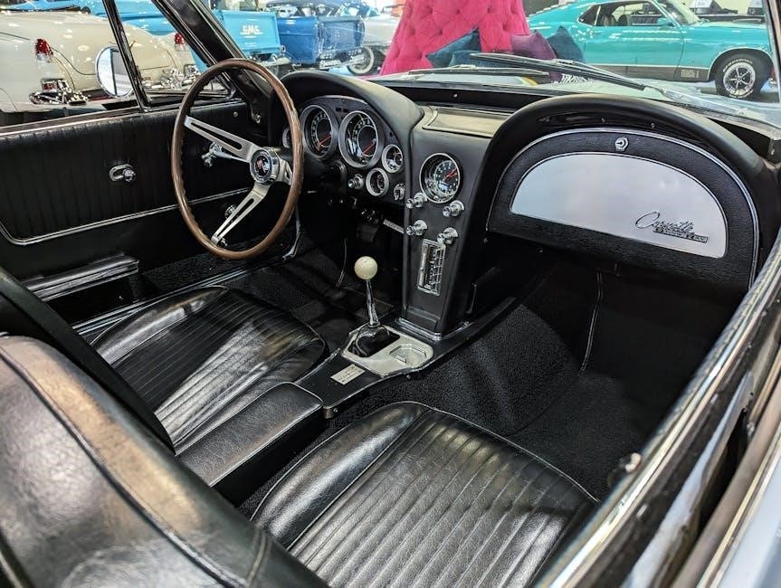
3.2 Periodic Inspection Checklist to Prevent Damage

Inspect the propeller for damage, check electrical connections for corrosion, and ensure fuel lines are free from leaks. Examine the cooling system for blockages and verify lubricant levels. Regularly clean or replace air and fuel filters to maintain efficiency. Addressing these issues promptly prevents costly repairs and ensures smooth operation. Always refer to your Yamaha service manual for a detailed checklist tailored to your motor model.

Troubleshooting Common Issues

Identify issues like engine overheating or reduced performance. The service manual provides diagnostic tools and repair steps to address these problems, ensuring optimal motor functionality and longevity.

4.1 Identifying and Diagnosing Common Problems

Common issues include engine overheating, reduced performance, or faulty ignition. The service manual provides detailed diagnostic steps, such as checking fuel flow, spark plugs, and cooling systems. It also outlines model-specific troubleshooting guides, like those for the F50 or FT50, ensuring accurate repairs. Regular inspections and adherence to maintenance schedules can help prevent these issues, extending the motor’s lifespan and reliability.

4.2 Tips for Repairing and Resolving Faults

Always use the correct tools and refer to the service manual for specific repair procedures. Regularly inspect fuel lines, spark plugs, and cooling systems to address issues early. For models like the F50 or FT50, ensure proper torque specifications and lubrication. The Seloc manual provides detailed guidance for both engine and lower unit repairs, ensuring accurate and efficient fault resolution to maintain performance and longevity.

Important Information for Yamaha Outboard Motor Owners

Always follow safety guidelines and operational instructions in the manual. Record your motor’s serial number for reference and ordering parts. Regular maintenance ensures reliability and longevity.

5.1 Safety Precautions and Operational Guidelines

Adhere to safety guidelines in the manual, such as wearing protective gear and avoiding overheated engines. Keep flammable materials away and ensure proper ventilation. Follow operational procedures carefully to prevent accidents. Regular inspections and maintenance are crucial for safe and efficient performance. Ignoring these precautions can lead to damage or personal injury, emphasizing the importance of strict adherence to the manual’s instructions.

5.2 Understanding the Serial Number and Its Significance

The serial number is crucial for identifying your Yamaha outboard motor, ensuring accurate repairs and maintenance. Locate it on the engine block or transom bracket. This unique identifier helps in ordering genuine parts and verifying the motor’s authenticity. It also serves as a valuable reference for anti-theft purposes. Always record the serial number and use it when requesting service or parts from Yamaha dealers to ensure compatibility and authenticity.

Models Covered in the Yamaha Outboard Motor Service Manual

The Yamaha service manual covers popular models like F50, Ft50, F60, Ft60, F70, F75, F80, and more, detailing maintenance for various configurations and years.

6.1 Overview of Popular Yamaha Outboard Motor Models

Yamaha offers a wide range of outboard motors, including the F50, Ft50, F60, Ft60, F70, F75, and F80. These models are known for their reliability and performance across various applications. The F50 and Ft50 are ideal for smaller boats, while the F60 and Ft60 provide higher power for medium-sized vessels. The F70, F75, and F80 models cater to larger boats, delivering robust power and efficiency. Each model is designed to meet specific needs, ensuring optimal performance for different marine activities.

6.2 Specific Engines Covered in the Manual

The manual covers a variety of Yamaha outboard engines, including the F50, Ft50, F60, Ft60, F70, F75, and F80 models. It also includes detailed information for 1-2-3-4 cylinder engines, V6, and V8 configurations. Additionally, the manual provides specifications and repair procedures for engines ranging from 2.5 to 350 horsepower, ensuring comprehensive coverage for both newer and older Yamaha outboard motor models.

Downloading and Accessing the Service Manual

The Yamaha outboard motor service manual can be downloaded from authorized Yamaha websites or platforms like Manual.ec. It is available in PDF format for easy access.

7.1 How to Find and Download the Yamaha Service Manual PDF

To find and download the Yamaha service manual PDF, visit official Yamaha websites or trusted platforms like Manual.ec. Search for your motor’s model or serial number to locate the specific manual. Once found, click the download link to access the PDF. Ensure you use reliable sources to guarantee the manual’s accuracy and safety for your outboard motor maintenance and repairs.

7.2 Sources for Reliable and Updated Manuals

Reliable sources for Yamaha outboard motor service manuals include official Yamaha websites, trusted platforms like Manual.ec, and authorized Yamaha dealers. These sources offer updated PDF manuals for various models, such as Yamaha 9.9, 6Y8, and CL5 Display. Additionally, platforms like Seloc provide detailed workshop manuals for Yamaha outboard motors, covering maintenance and repairs. Always verify the source’s authenticity to ensure you receive accurate and safe information for your motor.

Historical Context and Development of Yamaha Outboard Motors

Yamaha’s history is rich, marking significant milestones and leadership in outboard motors through continuous innovation and commitment to quality, enhancing performance and reliability over decades.

8.1 Brief History of Yamaha Outboard Motors

Yamaha introduced its first outboard motor in 1960, revolutionizing marine technology. Over the years, models like the 200HP V6 (1984) and the 4.2L V6 (2000) showcased innovation. Today, Yamaha offers high-performance options like the F350CETL and the 5.6L V8, maintaining its reputation for reliability and power.

8.2 Evolution of Technology in Yamaha Engines

Yamaha outboard motors have evolved significantly, from the first model in 1960 to today’s advanced engines. Innovations like variable camshaft timing and Lean Burn Control enhance performance and efficiency. Recent models, such as the 5.6L V8, showcase cutting-edge technology, ensuring reliability, power, and environmental compliance. These advancements reflect Yamaha’s commitment to innovation and meeting modern marine demands.

Common Repairs and Maintenance Tasks

Regular maintenance, such as oil changes and filter replacements, is essential to ensure optimal performance. Common repairs often involve the lower unit and propeller inspection, guided by the manual.

9.1 DIY Fixes and Maintenance Tips

Routine maintenance tasks include oil changes, filter replacements, and propeller inspections. DIY fixes often involve cleaning or replacing spark plugs and checking the lower unit for damage. Always use genuine Yamaha parts and follow the manual’s guidelines. Regular lubrication of moving parts and inspecting fuel lines can prevent costly repairs. Proper tools, such as a socket set and torque wrench, are essential for safe and effective DIY servicing.

9.2 When to Seek Professional Assistance

Complex issues like major engine overhauls or electronic system malfunctions require professional expertise. If DIY repairs are beyond your skill level or tools, consult a certified Yamaha technician. Damage to the lower unit or severe corrosion should also be addressed by professionals to ensure proper repair and maintain warranty validity. Always refer to the service manual for guidance on when specialized assistance is necessary.

Tools and Equipment Required for Servicing

Essential tools include wrenches, screwdrivers, pliers, and multimeters. Specialized tools like piston compressors and propeller pullers are required for advanced repairs.

10.1 Essential Tools for DIY Maintenance

For DIY maintenance, essential tools include wrenches, screwdrivers, pliers, and a multimeter. Safety gear like gloves and goggles is crucial. Use a torque wrench for precise bolt tightening and a socket set for engine components. A propeller wrench aids in propeller removal, while a compression test kit checks engine health. Always refer to the manual for specific tool recommendations to ensure safe and effective servicing.

10.2 Specialized Tools for Advanced Repairs

Advanced repairs require specialized tools like piston compressors, crankshaft pullers, and gear lapping tools. A propeller hub installer and bearing pullers are essential for lower unit overhauls. Diagnostic software and multimeters help troubleshoot electrical issues. Precision tools like micrometers ensure accurate measurements. These tools are often available through Yamaha dealerships or marine supply stores, ensuring compatibility and reliability for complex repairs.

Environmental Considerations for Outboard Motor Use

Always practice eco-friendly boating by minimizing fuel spills and properly disposing of waste. Regular maintenance prevents oil leaks and ensures efficient operation, reducing environmental impact.

11.1 Eco-Friendly Practices for Motor Usage

Eco-friendly practices include using biodegradable lubricants and avoiding oil spills. Regularly maintaining your Yamaha outboard motor ensures fuel efficiency and reduces emissions. Dispose of waste responsibly, such as recycling used oil and filters. Additionally, opt for low-emission Yamaha models, like those with four-stroke engines, which produce fewer pollutants. Always follow local environmental regulations and guidelines for sustainable boating.

11.2 Proper Disposal of Waste and Chemicals

Proper disposal of waste and chemicals is crucial for environmental protection. Dispose of used oil, filters, and batteries through authorized recycling centers. Avoid draining fluids directly into waterways. Follow local regulations for hazardous waste disposal. Yamaha recommends using eco-friendly materials and adhering to sustainable practices to reduce environmental impact. Always refer to the service manual for specific guidelines on handling and disposing of motor-related chemicals responsibly.

The Yamaha outboard motor service manual is essential for ensuring optimal performance and longevity. It provides detailed guidance for maintenance, repairs, and troubleshooting, covering all aspects of motor care.

Regularly referencing the manual ensures safety, efficiency, and environmental responsibility. Stay informed and adhere to its guidelines for years of reliable operation and sustained engine health.

12.1 Final Thoughts on the Importance of Proper Maintenance

Proper maintenance is crucial for optimal performance and longevity of Yamaha outboard motors. Regular checks and adherence to the service manual prevent mechanical issues, ensuring reliability and safety. Neglecting maintenance can lead to premature wear and reduced efficiency. Always follow guidelines for eco-friendly practices and safe operation. Consistent upkeep protects your investment and ensures years of trouble-free boating experiences.

12.2 Encouragement to Refer to the Manual Regularly

Regularly consulting the Yamaha outboard motor service manual ensures optimal performance, safety, and longevity. It provides detailed repair guides, troubleshooting tips, and maintenance schedules tailored to your motor. By following the manual, you can prevent costly repairs and extend the lifespan of your engine. Make it a habit to refer to the manual before any maintenance or repair task to ensure everything is done correctly and efficiently.

2012 honda cr v owners manual

Welcome to the 2012 Honda CR-V Owners Manual, your comprehensive guide to understanding and maintaining your vehicle. This manual covers operation, maintenance, safety features, and troubleshooting to ensure optimal performance and longevity of your SUV.

Safety Features and Precautions

The 2012 Honda CR-V Owners Manual emphasizes the importance of safety features and precautions to ensure a secure driving experience. It highlights the vehicle’s advanced safety systems, such as multiple airbags, anti-lock braking (ABS), and electronic stability control. The manual provides detailed instructions on proper seatbelt usage, child seat installation, and the correct operation of safety features. Additionally, it outlines precautions for driving in adverse conditions, loading cargo safely, and avoiding distractions while driving. Regular maintenance of safety components, such as brakes and tires, is also stressed to maintain optimal vehicle performance. By following the guidelines in this section, owners can minimize risks and ensure the safety of both passengers and pedestrians. This section serves as a critical resource for responsible and safe vehicle ownership.

Operating the Vehicle

The 2012 Honda CR-V Owners Manual provides clear instructions for starting the engine, using basic controls, and understanding driving modes. It ensures a smooth and efficient driving experience.

3.1 Starting the Engine and Basic Controls

Starting the engine of your 2012 Honda CR-V is straightforward. Insert the key into the ignition, turn it clockwise to the “START” position, and the engine will roar to life. Ensure the parking brake is engaged before starting. The manual also details the proper use of the immobilizer system for added security. Familiarize yourself with the basic controls, such as the steering wheel, pedals, and gearshift. The shift lever allows you to transition between park, reverse, neutral, drive, and low gear. Always check your mirrors and adjust your seat for optimal comfort and visibility before driving. For a smooth start, gradually release the brake and ease onto the accelerator. The manual emphasizes the importance of wearing seatbelts and ensuring all passengers are secured before moving the vehicle.

3.2 Driving Modes and Tips

Your 2012 Honda CR-V offers a smooth and responsive driving experience. The vehicle features a standard driving mode, designed for everyday use, and an “ECON” mode to enhance fuel efficiency. For challenging conditions, the CR-V includes a snow mode to improve traction on slippery surfaces. When driving in snow or mud, reduce speed and avoid sudden acceleration or braking. Always use the correct gear for the terrain to maintain control. To optimize fuel economy, drive at moderate speeds and maintain a consistent pace. Avoid idling for extended periods, as this wastes fuel. Use the cruise control on highways to maintain a steady speed and reduce fatigue. The manual also emphasizes the importance of proper tire pressure, as under-inflated tires can reduce efficiency and handling. By following these tips, you can enjoy a safe, efficient, and enjoyable driving experience in your CR-V.

Maintenance Schedule and Care

Regular maintenance is essential for your 2012 Honda CR-V’s reliability and longevity. Follow the recommended schedule for oil changes, tire rotations, and fluid checks to ensure optimal performance and prevent damage.

4.1 Recommended Maintenance Intervals

Regular maintenance is crucial for the longevity and performance of your 2012 Honda CR-V. The owners manual outlines specific intervals for routine services to ensure reliability and efficiency. Oil changes are recommended every 5,000 to 7,500 miles, depending on driving conditions. Tire rotations should be performed every 7,500 miles to ensure even wear and extend tread life. Spark plugs should be replaced at 30,000 miles and every 100,000 miles thereafter. Brake pads and rotors should be inspected every 15,000 miles, while belts and hoses should be checked every 50,000 miles. Fluid levels, including coolant, transmission, and brake fluid, should be monitored and replaced as specified. Following these intervals ensures optimal vehicle performance, fuel efficiency, and prevents costly repairs. Refer to the manual for a detailed schedule tailored to your driving habits and conditions.

4.2 DIY Maintenance Tips

Performing routine DIY maintenance on your 2012 Honda CR-V can save time and money while keeping your vehicle in excellent condition. Start by checking and maintaining proper tire pressure, as outlined in the manual, to improve fuel efficiency and handling. Regularly inspect and replace the air filter to ensure optimal engine performance. Oil changes are a straightforward DIY task; use the recommended viscosity grade specified in the manual. Check fluid levels, including coolant, brake, and transmission fluids, and top them off as needed. Inspect belts and hoses for signs of wear and replace them if necessary. Additionally, keep your battery terminals clean and secure to prevent electrical issues. For more complex tasks, consult the manual for guidance or consider seeking professional assistance. By following these tips, you can extend the life of your CR-V and maintain its reliability.

Troubleshooting Common Issues

The 2012 Honda CR-V Owners Manual includes a dedicated section for troubleshooting common issues, helping you identify and resolve problems efficiently. If the engine fails to start, check the battery connections, ensure the parking brake is fully disengaged, and verify the gearshift is in park. If warning lights illuminate on the dashboard, refer to the manual for specific meanings and recommended actions. For issues like unusual noises or vibrations, inspect tire pressure, brakes, and suspension components. If the vehicle overheats, check coolant levels and ensure the radiator is functioning properly. For transmission issues, ensure the fluid level is correct and consult the manual for guidance. If problems persist, contact a certified Honda technician for professional assistance. This section empowers owners to address minor issues independently while knowing when to seek expert help, ensuring your CR-V runs smoothly and reliably.

Technical Specifications

The 2012 Honda CR-V is equipped with a 2;4-liter inline-4 cylinder engine, producing 185 horsepower and 163 lb-ft of torque. It features a 5-speed automatic transmission with available front-wheel drive (FWD) or all-wheel drive (AWD). The fuel tank capacity is 15.3 gallons, offering an EPA-estimated 21 MPG in the city and 28 MPG on the highway for FWD models, and 20 MPG city/25 MPG highway for AWD models. The curb weight ranges from 3,305 to 3,455 pounds, depending on the trim level. The CR-V has a wheelbase of 103.1 inches and a ground clearance of 6.1 inches, providing ample space for passengers and cargo. The maximum towing capacity is 1,500 pounds when properly equipped. The vehicle’s compact design and efficient engineering make it a reliable choice for both urban and off-road driving. These specifications ensure the CR-V delivers a balance of performance, fuel efficiency, and versatility.

Warranty Information and Details

The 2012 Honda CR-V comes with a comprehensive warranty package designed to provide peace of mind for owners. The vehicle is covered by a 3-year/36,000-mile basic warranty, which includes repairs and replacements for parts and labor due to defects in materials or workmanship. Additionally, a 5-year/60,000-mile powertrain warranty covers the engine, transmission, and other powertrain components, offering extended protection for critical systems. Emissions-related components are covered under a 3-year/36,000-mile warranty, while select emissions components have an extended 15-year/150,000-mile coverage. The warranty information is outlined in detail within the owners manual, including terms, conditions, and limitations. It is essential for owners to review this section to understand their coverage and ensure proper maintenance practices. The manual also provides guidance on how to file warranty claims and what is required to maintain warranty validity; This comprehensive warranty package underscores Honda’s commitment to reliability and customer satisfaction.

Accessing the Owners Manual Online

The 2012 Honda CR-V Owners Manual is readily available for viewing or downloading online. Honda provides a convenient digital version of the manual on its official website, allowing owners to access it anytime. To view the manual, visit the Honda website, select your vehicle’s year and model, and navigate to the “Owners Manual” section. The manual is available in PDF format, enabling users to download it for offline use or print specific sections as needed. Additionally, third-party websites like ManualsLib or CarManualsOnline.info offer free access to the 2012 Honda CR-V Owners Manual, ensuring widespread availability. The online version is identical to the printed manual and includes hyperlinks for easy navigation. This digital accessibility ensures that owners can always reference the manual, even if the physical copy is unavailable. The online manual is also regularly updated to reflect the latest information, making it a reliable resource for CR-V owners. This feature underscores Honda’s commitment to providing seamless support for vehicle ownership.

Additional Resources and Downloads

Beyond the owners manual, Honda offers a variety of additional resources to enhance your ownership experience. The official Honda website provides access to service manuals, repair guides, and technical specifications for the 2012 CR-V. Owners can also find downloadable PDF versions of the manual, ensuring easy access on any device. Furthermore, Honda’s support website includes FAQs, troubleshooting guides, and software updates for integrated systems like navigation and infotainment. For more specialized needs, Honda offers detailed maintenance schedules and part catalogs through their dealerships or online portals. Additionally, third-party websites like ManualsLib and CarManualsOnline.info host comprehensive libraries of Honda manuals and guides, including the 2012 CR-V. These resources are designed to empower owners with in-depth knowledge and tools to maintain and customize their vehicle effectively. By leveraging these additional resources, CR-V owners can ensure their SUV remains in optimal condition and tailored to their preferences.